E-motor and e-drive test benches
Torque across load changes, regenerative operation and high speeds in electromagnetically demanding environments.
Test bench technology · Knowledge
A test bench reveals how a drive behaves under real loads. Torque data is fundamental to efficiency, load response, control, thermal assessment and durability.
Whether the test object is an e-motor, gearbox, drivetrain or endurance component, the measurement chain must remain stable across load changes, speed ranges and operating hours.
The challenge is usually the rotating shaft. The measurement point rotates while evaluation, data acquisition and test bench automation remain stationary. Contactless strain gauge telemetry connects both sides without wearing slip contacts.
Reproducible torque data
Contactless power and data transfer
For dynamic loads and endurance testing
Analog or CAN integration, depending on system
“Test bench” covers many different setups. Measurement point, dynamics, environment and evaluation target depend on the test object.
Torque across load changes, regenerative operation and high speeds in electromagnetically demanding environments.
Input and output torque for assessing efficiency, losses, load spectra and component loads.
Torque along the real load path, often combined with speed, temperature and condition data.
Durability testing of shafts, couplings, bearings and rotating assemblies over long operating periods.
Torque measurement under thermal load, vibration and changing operating states.
All of these test benches share a rotating measurement point. The underlying contactless transfer principle is explained in Contactless torque measurement.
Torque shows how a drive absorbs, transmits and sustains load. It is therefore one of the most important parameters for development, validation and release.
Comparing input and output torque makes losses and efficiency in gearboxes, e-drives and complete drivetrains measurable.
During load changes, acceleration ramps, regeneration and transient operating points, torque shows how quickly and steadily the test object responds.
Torque-time histories reveal peaks, load spectra and alternating loads used in service-life assessments.
Torque is often a control variable as well as an evaluation signal. Stable data supports reproducible test bench operation.
Noise, drift or transmission interruptions therefore affect more than a single test run. They also reduce confidence in conclusions about efficiency, durability and control behavior.
Comparable results across many runs and days.
Fast load changes and transient events must be captured rather than averaged away.
Transmission must not become an error source at high or rapidly changing rotational speeds.
Durability tests can run for hours, days or weeks without planned maintenance stops in the measurement chain.
Oil, temperature, vibration and electromagnetic interference are often part of normal operation.
Depending on the system, data must reach test bench automation through analog signals or CAN bus.
Torque is often evaluated together with temperature and rotational speed.
Two architectures are particularly relevant for rotating test bench shafts.
Strain gauges capture torsion, while mechanical slip contacts transfer the signal from the rotating to the stationary side. This can be sufficient for simple, accessible short-term setups. In endurance testing, at high speed or in harsh environments, wear, contact resistance and maintenance become operational risks.
The strain gauges are bonded directly to the shaft. The signal is digitized on the rotating side and transmitted without contact. Power and data pass between rotor and stator without slip contacts or a battery on the shaft.
Specialized alternatives include magnetoelastic and optical methods, each with its own operating limits. For many automotive, e-mobility and machinery test benches, the practical choice is between contacting transfer and contactless telemetry.
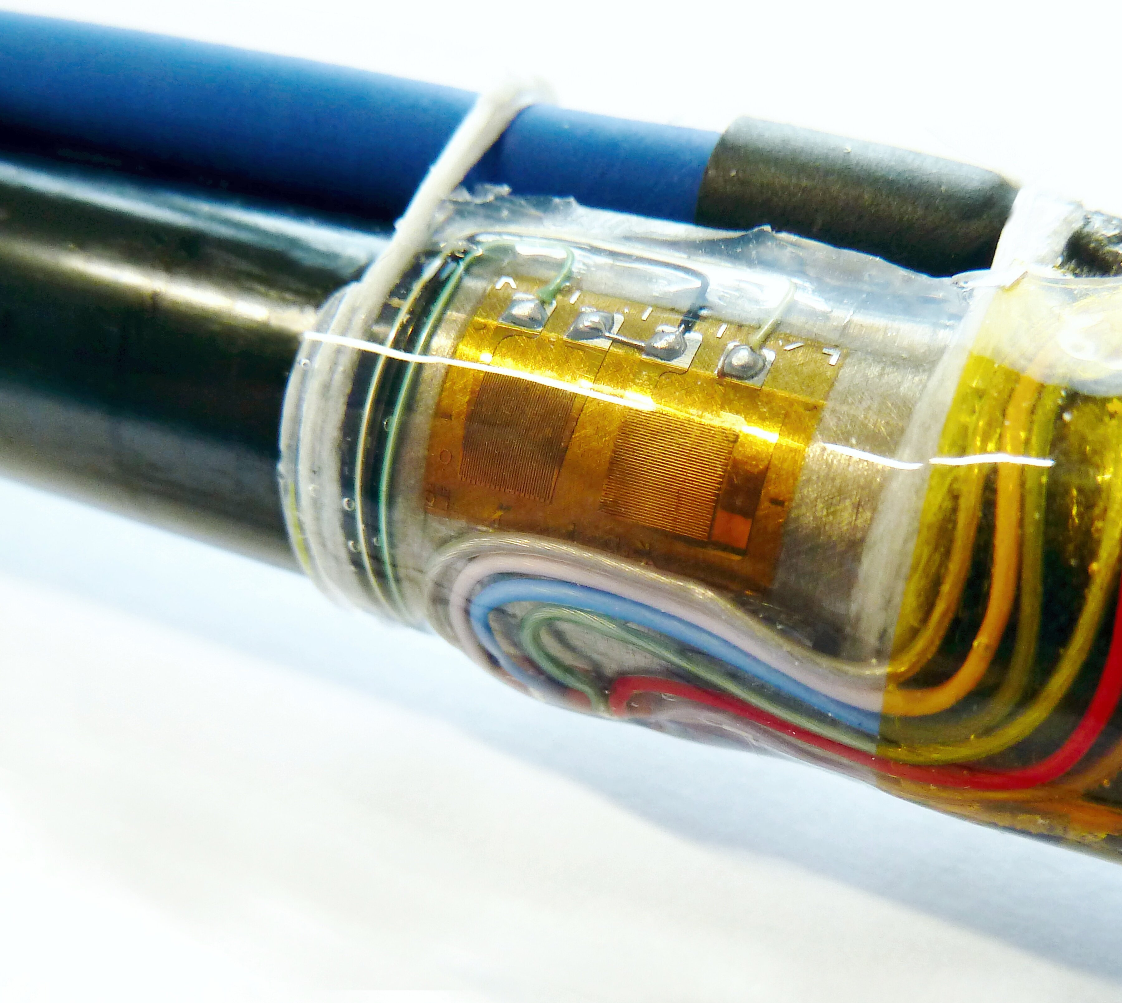
Removing brushes and slip contacts eliminates the mechanical contact point that can become a maintenance factor in endurance tests.
The signal transfer requires no scheduled contact cleaning or brush inspection.
Small strain gauge signals are digitized on the shaft before longer analog paths can pick up electromagnetic interference.
Contactless coupling avoids a mechanical contact zone that may become critical with speed, oil, vibration and temperature changes.
Depending on the task, combined or supplementary systems capture torque and temperature in the same load path.
Dynamic loads, high rotational speed and EMC exposure occur together. J1DB or J2D move signal conditioning onto the shaft; J2DT, JXTH or AT10 add temperature data where required.
Efficiency and loss analysis often requires input and output torque measurements. Multi-channel or multiple telemetry systems provide the required channels to suit the mechanical arrangement.
Torque is captured along the real load path over long operating periods and changing points. Wear-free transfer reduces planned intervention in the measurement chain.
Measurement-chain availability directly affects schedule and cost. A disturbed contact can compromise a complete test run.
AXON also supports the test bench task with strain gauge application on measurement shafts and measurement shaft application.
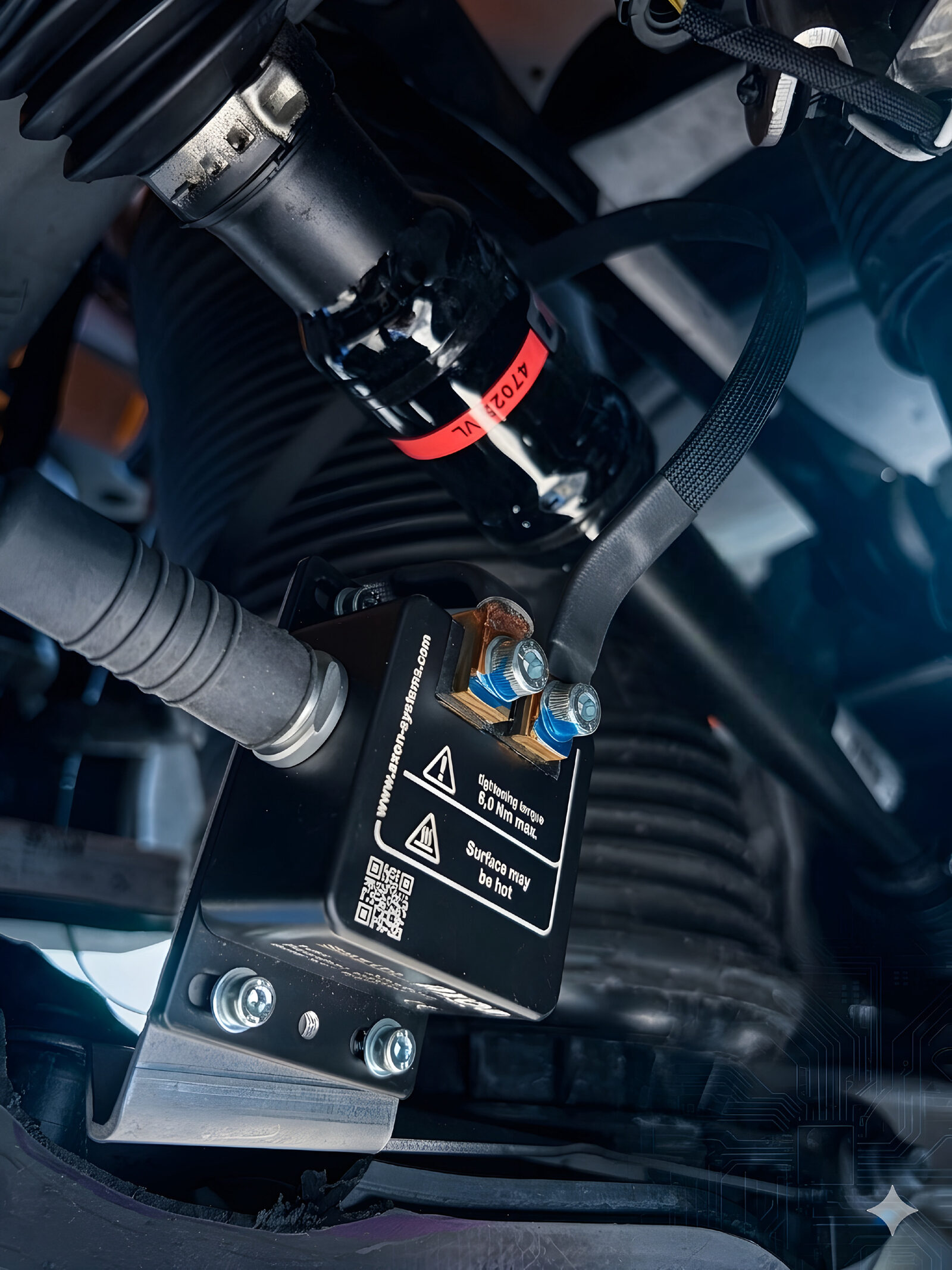
A test bench measurement does not end at the sensor. Data must reach acquisition and automation reliably. A typical AXON telemetry system has three components.
Mounted on the shaft, it supplies the strain gauge bridge, captures the signal and digitizes it at the measurement point. J1DB transmits strain gauge data at 16-bit resolution.
Supplies the rotor with power and receives data without contact. Product data for J1DB and JXTH specifies transfer distances from 1 to 80 mm; other systems use different values.
Processes received data and, depending on the system, provides analog or CAN bus outputs. Parameters such as rotor supply and signal quality support endurance-test diagnostics.
Sensitive signal conditioning remains close to the measurement point, while established interfaces connect it to the stationary test bench environment.
These inputs determine the measurement-chain design:
The more the task involves endurance operation, variable speed, harsh conditions and limited access, the stronger the case for contactless telemetry.
System selection follows the measurement task:
Digital 1-channel strain gauge telemetry for torque, force or strain on rotating components.
Product detailsTwo independent strain gauge channels, for example torsion and bending on one rotating shaft.
Product detailsOne strain gauge and one thermocouple channel for combined mechanical and thermal assessment.
Product detailsMulti-channel temperature telemetry with up to 16 thermocouple channels and measurement ranges up to 1,250 °C.
Product detailsPlug-and-play temperature measurement flange for compatible torque-flange test setups.
Product detailsThe solution starts with shaft, load, environment and interface rather than a device. AXON supports strain gauge application, mechanical integration and calibration through to a test-bench-ready measurement chain.
Torque underpins conclusions about efficiency, load behavior and service life. The decisive factor is not a single reading, but a measurement chain that remains repeatable and resistant to interference throughout the test.
Slip rings can be sufficient for simple, accessible short-term setups. For endurance operation, high speed, harsh environments or restricted access, contactless strain gauge telemetry provides the more robust architecture: capture and digitize the signal on the shaft, supply it with power without contact, and pass it cleanly to test bench automation.
Contactless strain gauge telemetry is often the better option for endurance testing because it has no wearing slip contacts and needs no battery replacement on the shaft. Slip rings can still suit short, accessible tests.
The control unit processes data received over the contactless link and, depending on the system, passes it to acquisition or control through analog outputs or CAN bus.
Yes. Efficiency and loss analysis often uses several channels or measurement points. The setup can use multi-channel systems or several telemetry systems.
Yes. J2DT combines one strain gauge and one temperature channel. JXTH and AT10 add multi-channel temperature acquisition to the measurement chain.
Often, yes. Suitability depends on geometry, material, installation space, load and environment. AXON evaluates strain gauge application and the integration of rotor, stator and control unit for the specific setup.
Useful inputs include test bench type, shaft geometry, torque and speed range, temperature range, media exposure, available space and required automation interface.
Test object, torque and speed range, temperature, installation space and required interface are enough for an initial technical assessment.